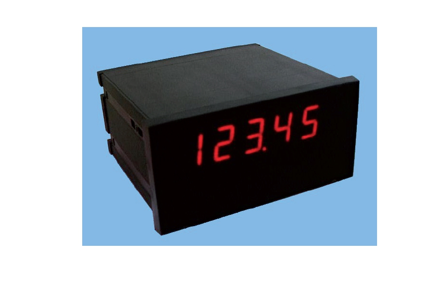
ANZEIGEEINHEIT
Datenempfang über Rs232, Rs485, RF 868 MHz.
Numerisches 5-stelliges Display, Höhe 20 mm. Box aus Noryl, selbstlöschend (UL 94 V1).
Kann an alle Geräte aus unserer Produktion angeschlossen werden.
Konfiguration und kundenspezifisches Protokoll mit PC-Software.
Installationsanleitung herunterladen ![]()
Bedienungsanleitung herunterladen ![]()
![]() Zur Vergrößerung auf das Bild klicken
Zur Vergrößerung auf das Bild klicken

| Stromversorgung | 230 V Wechselstrom, 50 / 60 Hz – Optional 115 V Wechselstrom, 50 / 60 Hz oder 12 / 24 V Gleichstrom | |
| Isolierung | Klasse II | |
| Installationskategorie | Kategorie II | |
| Betriebstemperatur | -10 / +40°C (14 °F / 104°F) Luftfeuchtigkeit Maximal 85% nicht kondensierend | |
| Lagertemperatur | -20 / +50°C (-4 / +122°F) | |
| Display | 5-stellige numerische rote LED mit 7 Segmenten (h 20 mm) | |
| Led | 8 5-mm-Anzeige-LEDs | |
| Tastatur | 5 mechanische Tasten | |
| Einbautiefe | 135 mm / 5.31 in | |
| Außenmaße | 144 x 72 x120 mm / 5.67 x 2.83 x 4.72 in (l x h x p) (DIN43700) | |
| Montage | Zum Einbauen in die Tafel (Bohrschablone 139 mm x 67 mm) | |
| Gehäusematerial | Selbstlöschender Noryl (UL 94 V1) | |
| Schutzklasse | IP 54 | |
| Anschlüsse | Abnehmbare Schraubklemmenblöcke 5,08 (Raster 7,5), serielle Anschlüsse am 9-poligen SUB-D-Stecker | |
| Kommunikationsschnittstelle | COM1: Rs232c, COM2: Rs422/Rs485 | |
| Maximale Kabellänge | 15m (Rs232c) und 1000m (Rs485) | |
| Serielle Protokolle | ASCII + kundenspezifisch programmierbare Protokolle | |
| Baudrate | Aus 1200 zu 115200 anwählbar | |
| Schnittstelle RF 433MHz, Option | Gekoppelter Betrieb mit, mit der Transmitterwaage abgestimmtem Transmittermodul | |
| Anzahl RF-Kanäle | Bis zu 10 Kanäle wählbare im 868-MHz-Band für die Installation mehrerer Systeme im selben Bereich | |
| Durchschnittliche Reichweite | 100 m auf freiem Feld | |
| Normkonform | EN61000-6-2, EN61000-6-3, EN61010-1 | |
| Typ | Speisung Klemmleiste 2P Schritt 7.5 |
| Länge | ND |
| 1 | 230V~ Line |
| 2 | 230V~ Neutral |
| Typ | Verbinder D-SUB 9P |
| Länge | ND |
| 1 | NC |
| 2 | RS232 Rx |
| 3 | RS232 Tx |
| 4 | RS422 TX+ |
| 5 | GND |
| 6 | RS422 TX- |
| 7 | RS422 RX- |
| 8 | RS232 CTS |
| 9 | RS422 RX+ |
General precautions to be followed in the installation and assembly of load cells: